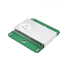
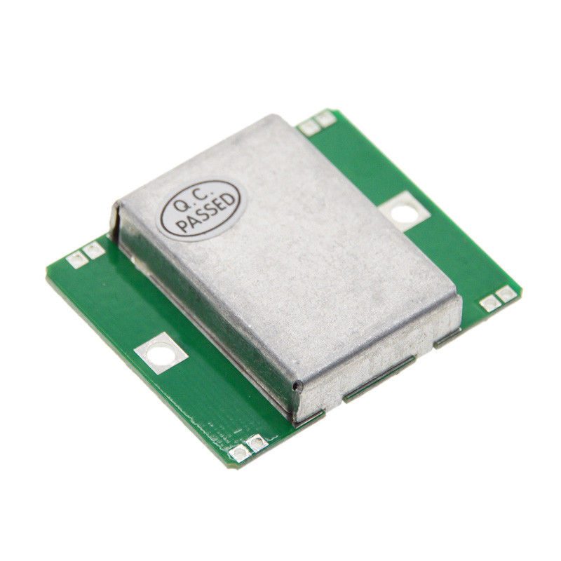
Microwave Doppler Wireless X-band Radar Detector Probe Sensor Module 10.525GHz (HB100). HB100 Microwave Module User Manual
WARNING
Please use this product correctly under the conditions specified and permitted in this manual.
External environment and input that are beyond the tolerance of this product will cause irreparable damage to it
Without special circumstances, destructive and extreme tolerance tests should not be performed on this product.
Such tests will also cause irreversible damage to it.
Please use a low-voltage soldering iron and ground the soldering iron reliably when soldering the DIP PAD.
You need to solder the side with circuit traces or copper cladding!!
==================================
The HB100 microwave module uses the principle of Doppler radar.
The microwave moving object detector designed is mainly used for automatic door control opening
Security system, ATM automatic cash machine automatic video control system
HB100 is a standard
10.525GHz microwave Doppler radar detector, this detection method is similar to
Compared with the detection method, it has the following advantages:
1. Non-contact detection;
2. Not affected by temperature, humidity, noise, airflow, dust, light, etc., suitable for harsh environments;
3. Strong anti-RF interference capability;
4. The output power is small and does not pose any harm to the human body;
5. Long distance: detection range exceeds 20 meters
Introduction to Doppler Principle: Doppler theory is based on time. When a radio wave hits an object during its travel, it will be reflected, and the frequency of the reflected wave will change with the movement of the object. If the position of the object hit by the radio wave is fixed, the frequency of the reflected wave should be equal to the frequency of the transmitted wave. If the object moves in the direction of transmission, the reflected wave will be compressed, that is, the frequency of the reflected wave will increase; otherwise, the frequency of the reflected wave will decrease.
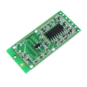
The microwave detector designed according to the Doppler principle consists of a FET medium DRO microwave oscillator (10.525GHz), a power divider, a transmitting antenna, a receiving antenna, a mixer, a detector and other circuits (Figure 2). The transmitting antenna transmits microwaves outward in a directional manner. When it encounters an object, it is reflected. The reflected wave is received by the receiving antenna and then mixed with the oscillating wave in the mixer. The low-frequency signal after mixing and detection reflects the speed of the object.
Compared with using lower frequency waves, using 10.525GHz microwaves has the following advantages: 1. Microwave antennas have good directivity when transmitting, so it is easy to control the range of microwave probes. 2. Microwaves are more easily attenuated, absorbed and reflected during transmission, and will be blocked when encountering obstructions such as walls, so objects other than walls and other obstructions will have little interference with them.
Power supply: There are two modes for powering HB100: continuous DC power supply (CW) mode and pulse power supply (PW) mode. The voltage range of HB100 is 5V±5%. The typical current is 35mA (typical value) when working in continuous DC power supply (CW) mode. When working in low duty cycle pulse power supply (PW) mode, it is recommended to provide HB100 with 5V, pulse width between 5μs and 30μs (typical value is 20μs), and frequency of 2 to 4kHz (typical value is 2.0kHz). The average current is 1.2mA to 4mA when the duty cycle pulse power supply is 3 to 10%.
The pulse supply voltage must be between 4.75V and 5.25V. The flatness of the pulse tip will affect the detection capability of HB100. When the supply voltage exceeds 5.25V, its reliability will be reduced and may cause RF output outside the nominal frequency and permanent damage to the circuit.
RF output: In all recommended working modes, the RF power output of HB100 is very low and operates within a safe range that does not pose any harm to the human body. When working in continuous DC power supply (CW) mode, the total output power is less than 15mW. The output power density is 1mW/cm2 at 5mm and 0.72μW/cm2 at 1m. When working in pulse power supply mode with a 5% duty cycle, the power density is reduced to 50μW/cm2 and 0.036μW/cm2 respectively.
IF output: When an object moves radially relative to the antenna surface of HB100 (the side not made of aluminum shielding cover is the antenna surface) at a speed of 1m/s within the effective detection range of HB100 , the IF output of HB100 is 72Hz/s, and the pulsating output frequency of IF is approximately linearly related to the relative radial moving speed of the object. The output amplitude of IF is related to the size and distance of the object. When a tester weighing 70kg and 170cm in height moves radially relative to HB100 at a speed of 1m/s at a distance of 1m from HB100, the output of IF is a pulsating signal of 5mV and 72Hz/s, and the output amplitude of IF is approximately inversely proportional to the square of the distance.
Note : 1. The detection range depends on the reflectivity and size of the target and the signal-to-noise ratio.
2. The Doppler velocity at 10.525 GHz is 31 Hz/mph
3. The module must be installed with its antenna surface (the side not covered by the aluminum shield) facing the detection area. Users can also adjust the direction to achieve the best coverage area.
Simple fault diagnosis: The IF output of HB100 is easily broken down during welding. Use the diode range of the multimeter to measure the voltage drop between IF and GND and between GND and IF. Under normal circumstances (VIF-GND and VGND-IF) are both around 0.25V.
There are no reviews yet.